
Mesh Rider® Radio Platform
Mesh Rider® Radio provides resilient, low latency, long-range, high-throughput links to implement industrial-grade private wireless mobile mesh Networks.
Helix: Federal M1-M6 Bands, 1625-2510 MHz Band
Our Helix Mesh Rider® Radios operates on six bands (M1-M6) within 1625-2510 MHz, which provides global coverage so systems can be deployed without requiring multiple SKUs. This frequency range removes a large operational complexity for government customers who have deployments around the world. Moreover, license free 2.4 GHz band is also covered to further increase the global coverage. Helix Mesh Rider® Radio J/F-12 certification #13258
Key Features
Low SWaP
Performance RF
Fast Integration
Long Range

Mesh
Frequency Flexibility

C&C + Video
Affordable
Mesh Rider®
A small, high performance mesh radio designed for unmanned systems. The Embedded Mesh Rider® Radio is a robust radio incorporating all the benefits of Mesh Rider in a SWaP (Size, Weight and Power) optimized form factor.
Common Integrations

Drones/UAVs
UGVs
AMRs
Mobile Robotics
Link Distance
Mesh Rider® Radio’s Mesh Rider waveform has been field proven by customer to provide a link over 100km. The link distance of each system, however, depends on many factors: mainly antenna gain, line of sight obstructions, Fresnel zone clearance, and environmental noise conditions. The chart below give an indication of radio’s performance in a typical configuration.
| PERFORMANCE OVERVIEW | |
|---|---|
| Protocol Compatibility | Fully compatible with Wi-Fi (IEEE 802.11b,g,n) |
| Unobstructed Operating Range with 3 dBi Antennas on both ends (Indicative) | >8 Km (>5 Miles) |
| Data Throughput at 10-meter range with Attached 3 dBi Antennas (Indicative) | 40 Mbps (20 MHz Channel) 20 Mbps (10 MHz Channel) 10 Mbps (5 MHz Channel) 6 Mbps (3 MHz Channel) |
| Over the Air Data Encryption | FIPS 140-3 Level 1 Compliant |
| Operating Modes | WiFi Radio: AP, Client Mesh Rider Radio: Mesh, WDS AP, WDS Client Bridged or Internet Gateway with NAT |
| Command & Control Channel | Ultra-Reliable Low Latency Channel (URLLC). Latency 1.5-10 ms |
| Video Channel | Optimized video streaming with Unicast and Multicast transmission |
| RF SPECIFICATIONS | |
|---|---|
| Frequency Range | 1625-2510 MHz |
| Operating Bands (Software Selectable) | M1 = 1625-1725 MHz M2 = 1780-1850 MHz M3 = 2025-2110 MHz M4 = 2200-2290 MHz M5 = 2310-2390 MHz M6 = 2400-2510 MHz |
| Advanced Band Filters | Dedicated SAW filters for each band for high interference immunity |
| Max RF Power at SMA port (Software control) Each radio individually calibrated | 1.3W (31 dBm) @ MCS 0,8 1.0W (30 dBm) @ MCS 3,11 0.8W (28 dBm) @ MCS 5,13 250mW (24 dBm) @MCS 7,15 |
| Channel Sizes (Software Selectable) | 3, 5, 10, 20 MHz |
| Radio Data Rate | Auto adapting Modulation Coding Scheme (MCS0-15) |
| Antenna Signal Strength | -30 to -90 dBm (Recommended), Absolute Maximum= +12 dBm |
| Nano & Mini-OEM: Receiver LNA Gain | >15 dB |
| RF Power Control | In 1 dBm steps, Tolerance ±1 dBm |
| Automatic Transmit Power Control (ATPC) | Intelligently adjusts the transmit power for very close range operation |
| Integrated Antenna Port Protection | Able to withstand open port, >10 KV (contact) and >15KV (open air discharge) as per IEC-61000-4-2 |
| Wireless Error Correction | FEC, ARQ |
| NETWORKING SPECIFICATIONS | |
|---|---|
| Mesh Router | Self-Forming/Self-Healing, Peer to Peer |
| Custom Software Package Manager | Image Builder, OPKG, ipk |
| Radio Management | Web GUI (HTTPs), SSH, SNMP and JSON-RPC |
| Access control | Password, MAC, IP, Port filtering |
| Supported Protocols | IPv6, QoS, DNS, HTTPS, IP, ICMP, NTP, DHCP |
| Software Upgrade | Over the air software upgrade supported |
| ADDITIONAL MESH RIDER RF SPECIFICATIONS | |
|---|---|
| Radio Data Rates (Dynamic Link Auto Adaptation) | MCS15 = 64QAM (5/6) MCS14 = 64 QAM (3/4) MCS13 = 64 QAM (2/3) MCS12 = 16QAM (3/4) MCS11 = 16QAM (1/2) MCS10 = QPSK (3/4) MCS9 = QPSK (1/2) MCS8 = BPSK (1/2) MCS7 = 64QAM (5/6) MCS6 = 64 QAM (3/4) MCS5 = 64 QAM (2/3) MCS4 = 16QAM (3/4) MCS3 = 16QAM (1/2) MCS2 = QPSK (3/4) MCS1 = QPSK (1/2) MCS0 = BPSK (1/2) |
| Rx Sensitivity (3 MHz Channel BW) | -100 dBm @ MCS 0 -97 dBm @ MCS 1 -95 dBm @ MCS 2 -92 dBm @ MCS 3 -87 dBm @ MCS 4 -85 dBm @ MCS 5 -82 dBm @ MCS 6 -79 dBm @ MCS 7 -97 dBm @ MCS 8 -93 dBm @ MCS 9 -91 dBm @ MCS 10 -88 dBm @ MCS 11 -84 dBm @ MCS 12 -80 dBm @ MCS 13 -79 dBm @ MCS 14 -78 dBm @ MCS 15 |
| Rx Sensitivity (5 MHz Channel BW) | -98 dBm @ MCS 0 -95 dBm @ MCS 1 -93 dBm @ MCS 2 -90 dBm @ MCS 3 -85 dBm @ MCS 4 -83 dBm @ MCS 5 -80 dBm @ MCS 6 -77 dBm @ MCS 7 -95 dBm @ MCS 8 -91 dBm @ MCS 9 -89 dBm @ MCS 10 -85 dBm @ MCS 11 -82 dBm @ MCS 12 -78 dBm @ MCS 13 -77 dBm @ MCS 14 -76 dBm @ MCS 15 |
| Rx Sensitivity (10 MHz Channel BW) | -96 dBm @ MCS 0 -93 dBm @ MCS 1 -91 dBm @ MCS 2 -88 dBm @ MCS 3 -83 dBm @ MCS 4 -81 dBm @ MCS 5 -78 dBm @ MCS 6 75 dBm @ MCS 7 -93 dBm @ MCS 8 -89 dBm @ MCS 9 -87 dBm @ MCS 10 -84 dBm @ MCS 11 -80 dBm @ MCS 12 -76 dBm @ MCS 13 -75 dBm @ MCS 14 -74 dBm @ MCS 15 |
| Rx Sensitivity (20 MHz Channel BW) | -93 dBm @ MCS 0 -90 dBm @ MCS 1 -88 dBm @ MCS 2 -85 dBm @ MCS 3 -80 dBm @ MCS 4 -78 dBm @ MCS 5 -75 dBm @ MCS 6 -72 dBm @ MCS 7 -90 dBm @ MCS 8 -86 dBm @ MCS 9 -84 dBm @ MCS 10 -81 dBm @ MCS 11 -77 dBm @ MCS 12 -73 dBm @ MCS 13 -72 dBm @ MCS 14 -70 dBm @ MCS 15 |
| Receive Noise Figure | +4 dB |
| Receive Adjacent Channel Rejection (ACRR) | >34 dB @ MCS0 for 20 MHz channel (Typ) |
| Transmitter Adjacent Channel Leakage Ratio (ACLR) | 28 dBr (Fc ± ChBW) |
| Transmitter Spurious Emission Suppression | < 40 dBc |
| Frequency Accuracy | ±10 ppm max over life |
| REGULATORY INFORMATION | |
|---|---|
| J/F-12 Certification | J/F-12 #13258 |
| FCC ID | In progress |
| Industry Canada (IC) | In progress |
| CE | In progress |
| Regulatory Requirements | Designed and verified to meet various regulatory requirements. Formal testing and approval are required for the Integrator’s antenna type. The integrator is responsible for obtaining all regulatory approvals in target markets for the finished product. |
| RoHS/WEEE Compliance | Yes. 100% Recyclable/Biodegradable packaging |
| MESH RIDER RADIO HELIX - 1625 - 2510 MHz | ||
|---|---|---|
| Antenna Connection | 1x MMCX-Female connectors | 2x MMCX-Female connectors |
| DC Power Consumption | Bands M1-M3: Average 4W (50% Tx/Rx duty cycle), 6W Peak Tx power @ max range, 2.7W Rx mode Bands M4-M6: Average 3W (50% Tx/Rx duty cycle), 4.5W Peak Tx power @ max range, 1.2W Rx mode | Bands M1-M3: Average 7W (50% Tx/Rx duty cycle), 10W Peak Tx power @ max range, 4.5W Rx mode Bands M4-M6: Average 5W (50% Tx/Rx duty cycle), 8W Peak Tx power @ max range, 2W Rx mode |
| Dimensions | RF Board: 47 x 28 x 6.5 mm Baseband Board: 47 x 28 x 5 mm | RF Board: 47 x 51 x 6.5 mm Baseband: 47 x 28 x 5 mm |
| ESD Protection | IEC 61000-4-2 test criteria, Level 3 (±6KV) for Contact Discharge and Level 4 (±15KV) for Air Discharge |
|
| Form Factors | 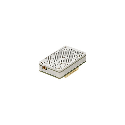 | 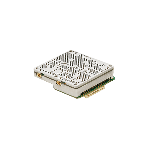 |
| Host Interfaces | Ethernet (100 Base-T), USB-Dev, 1x UART (3.3V) | Ethernet (100 Base-T), USB-Dev, 1x UART (3.3V) |
| Ingress Protection | IP 50, Dust Protected, No Liquids | |
| Integrated CPU | MIPS 24K, 540 MHz, 32MB Flash, 64MB DDR2 RAM |
|
| Integrated GPS (Optional) | N/A | N/A |
| Life Cycle Planning | Extended lifespan with 7 years guaranteed availability | |
| Model Code | RM-2025-61N3 (1x1, Industrial) | RM-2025-62M3 (2x2, Industrial) |
| MTBF | >235k hours (25 years) | |
| Operating Voltage | 5V ± 5% | 5V ± 5% |
| Relative Humidity | 5% to 95% noncondensing |
|
| Reliability | Extreme Reliability, IPC Class 2 standard with Class 3 options | |
| Shock and Vibration Resistance | Compliant to MIL-STD-810H for high shock and vibration |
|
| Temperature range (Non-Operating) | -40°C to +100°C |
|
| Temperature range (Operating) | Industrial: -40°C to +85°C, Commercial: -10°C to +65°C External Temp: Up to +40°C (Wearable) System’s thermal design should ensure that the radio’s case temperature is maintained within these specifications. |
|
| Weight | 15-30 grams (depending on mounting configuration) | 25-40 grams (depending on mounting configuration) |
Loading...